Geomembrane Electrical Leak Location (ELL) Surveys
Electrical leak location surveys for geomembranes—exposed, soil/gravel-covered and water-covered—performed in accordance with ASTM D6747, D7007, D7703 and D7953.
Engineering Background
High-density polyethylene (HDPE) geomembranes are the workhorse hydraulic barrier in landfills, mining heap-leach pads, water-conservancy works, chemical containment, metallurgical impoundments, water and wastewater facilities, ornamental water features, aquaculture and municipal infrastructure. Their chemical resistance, mature manufacturing, weldability and well-documented field performance make them the default choice for primary containment. Defects—pinholes, punctures, slits, tears and seam imperfections—are nevertheless introduced during manufacture, transport, deployment and overburden placement, and any of these can compromise the liner's hydraulic-barrier function. Electrical Leak Location (ELL) surveys, conducted in accordance with ASTM D6747 (Standard Guide for Selection of Techniques for Electrical Detection of Potential Leak Paths and Leaks in Geomembranes), provide a quantitative, defensible means of demonstrating liner integrity as part of a Construction Quality Assurance (CQA) programme.
- Pre-cover stage: arc-testing method (ASTM D7953) for early detection of pinholes from manufacturing, transport and welding
- Post-cover stage: dipole method (ASTM D7007 / CJJ/T 214-2016) for locating mechanical damage beneath earthen or aqueous overburden
- Exposed-geomembrane leak location—arc testing and water-puddle methods (ASTM D7953 / D7703)
- Soil- and gravel-covered geomembrane leak location—dipole survey on a regular grid
- Water-covered geomembrane leak location per ASTM D7007 (wading, towed-array and survey-vessel modes)
- CQA-grade survey reports with georeferenced defect coordinates and remediation guidance
Principle & Method
Field experience confirms that even rigorous CQA programmes do not eliminate post-deployment leakage; once the geomembrane is covered, conventional visual inspection cannot localise defects. Electrical Leak Location exploits the dielectric contrast between the insulating geomembrane and the conductive media on either side of it. A controlled electric field is established across the liner, any breach forms a low-resistance current path, and the resulting local field anomaly is mapped to defect coordinates. Industry data show that the great majority of leaks originate during construction—from material handling, deployment and overburden placement—rather than from primary seam failure, so ELL surveys both during deployment (exposed-liner phase) and after overburden placement provide the most cost-effective coverage of the defect population and substantially raise the reliability of the completed containment.
Typical Scenarios & Diagrams
Exposed Geomembrane — Arc Testing (ASTM D7953)
Geomembranes accumulate pinholes, punctures and cuts during manufacture, transport and deployment. Even small pinholes, if sufficiently numerous, drive cumulative leakage above the design Action Leakage Rate (ALR). Although the dipole method (ASTM D7007) is routinely used after overburden placement, its sensitivity to micro-defects is limited; pre-cover ELL surveys are therefore essential.
Legacy water-lance and water-puddle methods (ASTM D7002 / D7703) are still used for QA/QC on exposed liners, but their applicability is constrained by site conditions. The arc-testing method, conducted in accordance with ASTM D7953 (Standard Practice for Electrical Leak Location on Exposed Geomembranes Using the Arc Testing Method), is preferred for dry exposed liners and for liners covered only by non-conductive porous synthetics (e.g., geotextiles). It requires a conductive subgrade—typically a Geosynthetic Clay Liner (GCL) or a Compacted Clay Liner (CCL)—or, for double-liner systems, a wetted geocomposite drainage layer between the membranes. High voltage is impressed above the geomembrane and grounded to the underlying conductor; a hand-held conductive brush sweeps the surface, and current discharge through any breach completes the circuit, producing a visible arc together with audible and visual alarms that pinpoint the defect.
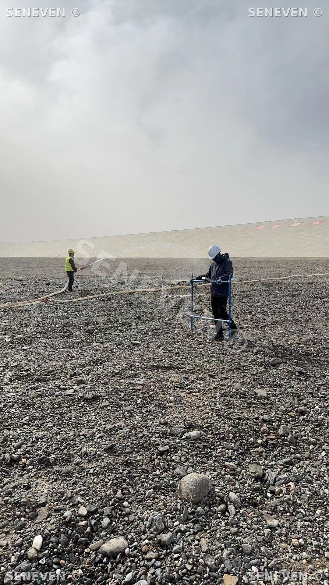
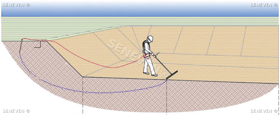
Soil- and Gravel-Covered Geomembrane — Dipole Survey (ASTM D7007)
After protective soil or gravel is placed over the geomembrane, heavy construction equipment becomes the principal damage agent. A post-construction integrity ELL survey is the most cost-effective means of locating defects introduced during overburden placement and proof-loading. Conducted in accordance with ASTM D7007 (Standard Practices for Electrical Methods for Locating Leaks in Geomembranes Covered with Water or Earthen Materials) and the Chinese specification CJJ/T 214-2016 (Technical Specification for Leak Detection of Anti-seepage Geomembrane in Municipal Solid Waste Landfills), the dipole method energises the cover material above the liner and grounds the receiving electrode below the liner, establishing a stable far-field potential distribution.
An intact geomembrane yields a uniform field; each breach acts as a local current source whose dipole signature is captured by reference and roving electrodes on a regular survey grid. Acquired potentials are recorded together with georeferenced station coordinates, archived locally and uploaded to a cloud analytics platform that returns defect coordinates and 2-D / 3-D potential-field maps for QA evaluation and maintenance planning. Modern acquisition units record longitudinal and transverse differential potentials together with single-electrode voltages, enabling sub-metre defect localisation.
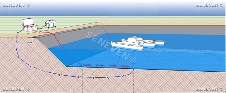
Water-Covered Geomembrane — In-Water ELL Survey (ASTM D7007)
For impoundments that cannot be drained, ELL surveys are conducted on the water-covered liner in accordance with ASTM D7007 (Standard Practices for Electrical Methods for Locating Leaks in Geomembranes Covered with Water or Earthen Materials).
Wade-in survey. In shallow water (≤ 50 cm), the surveyor wades the impoundment with a hand-held probe and acquires data on a regular grid, locating pinholes, seam defects, patches and weld imperfections; suspect points are buoy-marked. Field data are uploaded to the cloud platform for post-processing, recovering defects that may have been missed in real time and improving the completeness and reliability of the survey.
Towed-array survey. Where water depth exceeds 50 cm, or the impoundment contains hazardous liquids, chemicals, sludges or thick sediments that preclude wading, a floating sensor array is towed across the basin on lines. The acquisition unit logs the electric-field response and the GNSS coordinates of each station, from which defect locations are computed.
Survey-vessel mode. At water depths greater than 1 m, a programmable survey vessel runs pre-planned tracklines while sensors are deployed at depth-controlled stand-off (no more than 50 cm above the liner) to ensure data fidelity while preserving operator and equipment safety.
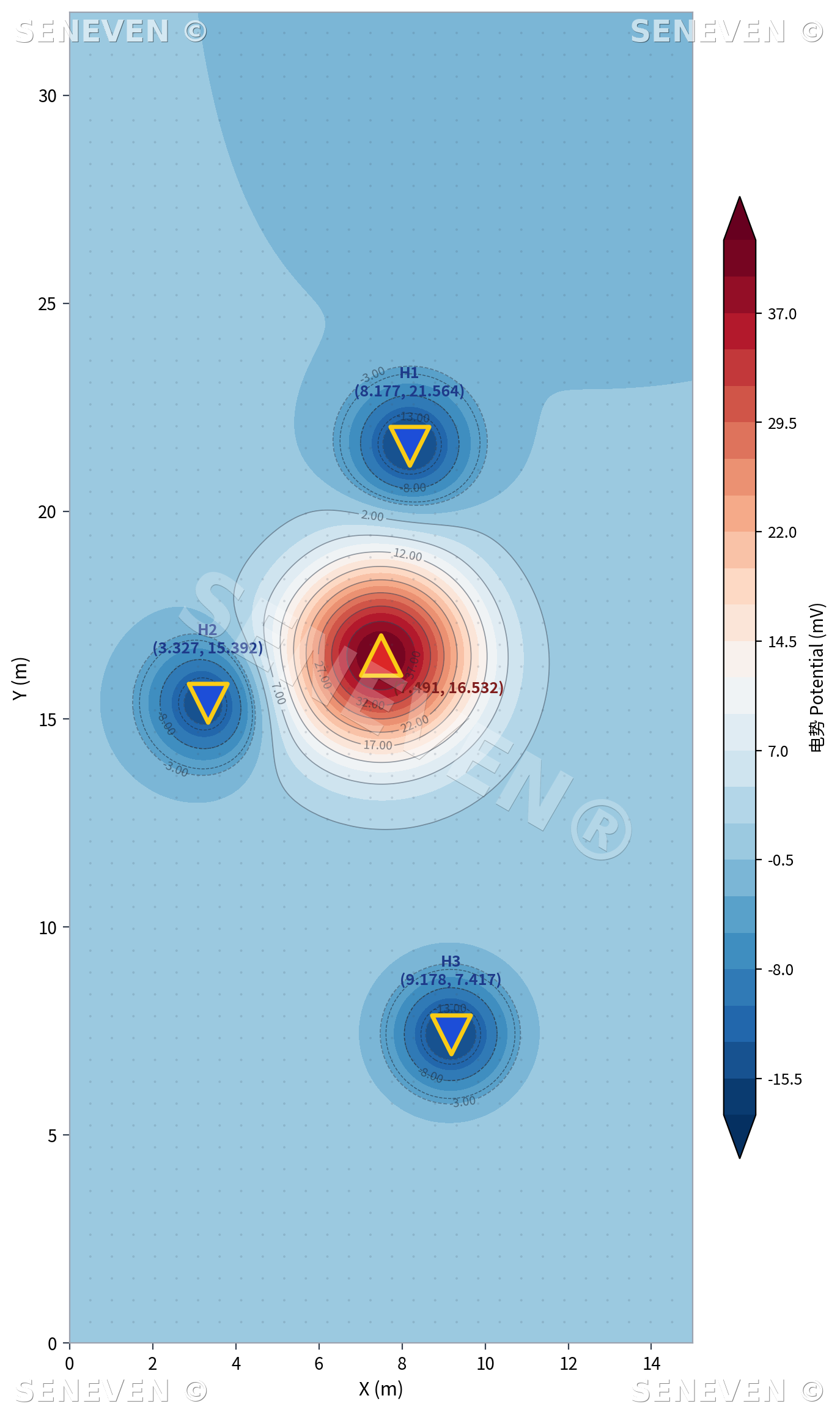
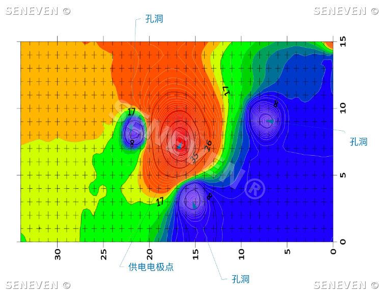
2D Equipotential Contour Map
With a steady-state field established across the geomembrane, the system collects potential measurements across the site and inverts them into a 2-D equipotential contour map.
An intact liner produces smooth, evenly spaced contours; a breach forms a local low-resistance path that warps the field, and the contours bunch and bend toward the defect — letting operations crews triangulate leak location and plume extent at a glance.
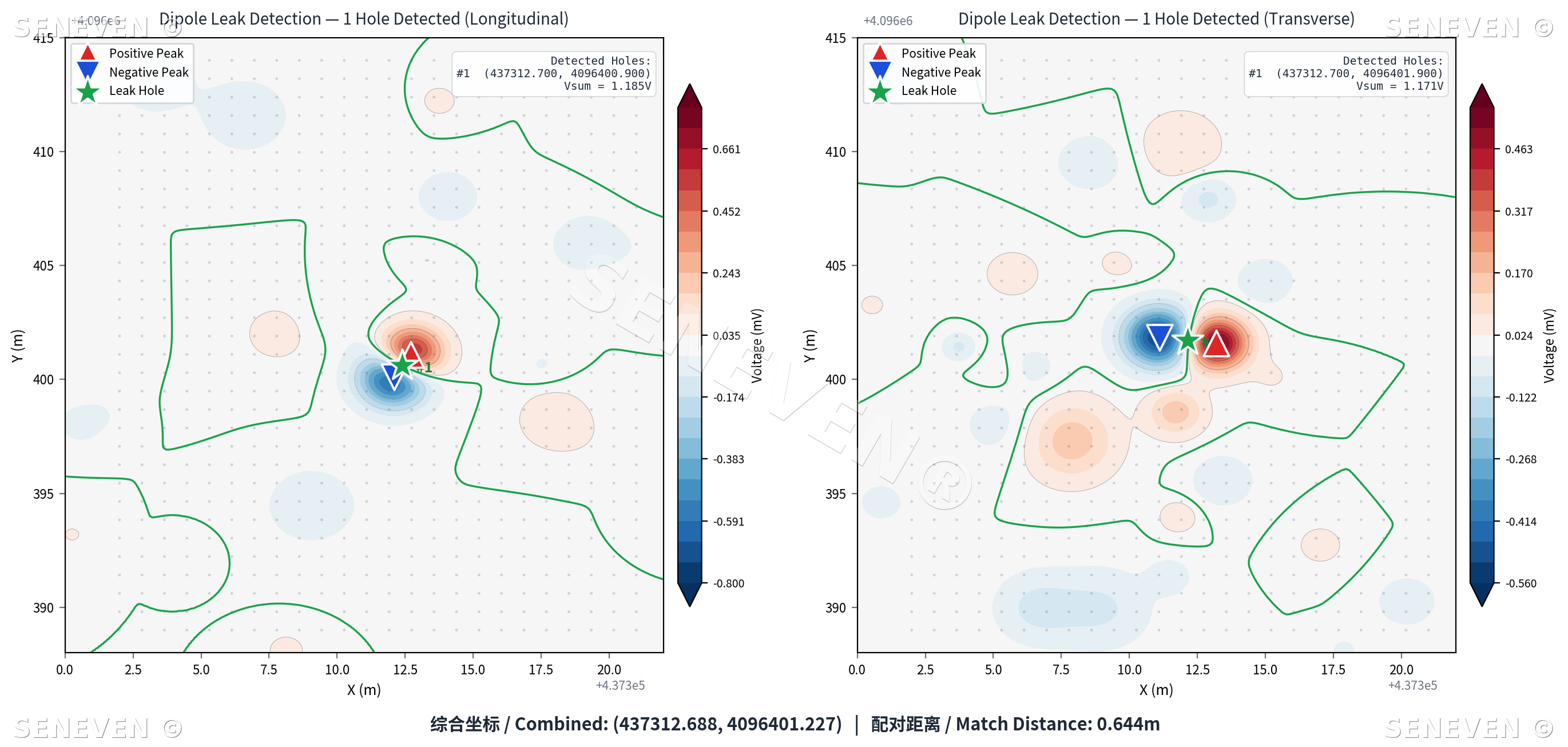
Dipole Cross-Section Response
Following ASTM D7007 dipole-method workflow, paired probes are stepped above the liner along a grid and the potential difference is logged at every station.
When the dipole crosses directly over a breach, the cross-section trace exhibits the classic positive-negative inversion with a clean zero-crossing — the electrical fingerprint of a defect. The same trace estimates the defect depth, guiding targeted excavation and confirmation in the field.
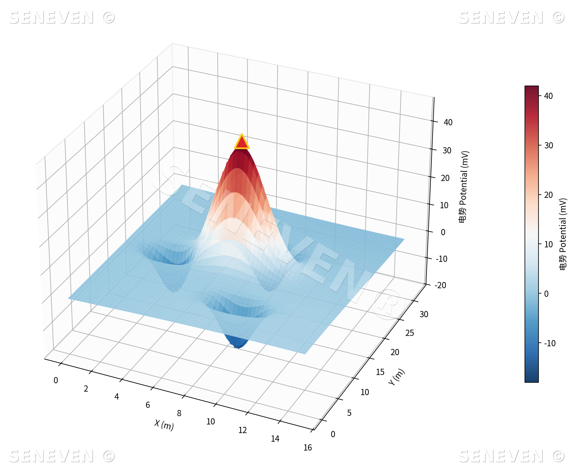
3D Potential-Field Surface
All site observations are aggregated on the cloud platform into a 3-D potential-field surface.
A defect appears as a sharp peak on the surface — peak height encoding leak intensity, peak position the defect coordinates. Combined with contour projections, cross-section slices and time-series comparison, every leak is turned from a hidden flaw into quantifiable, auditable engineering data.
Need technical support?
Contact the SENEVEN engineering team for a tailored detection or monitoring scope, scaled to your project type, footprint and field conditions.